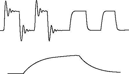
PURPOSE: Plot a graph of the damped oscillations in a very low frequency RLC resonant circuit.
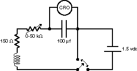
DESCRIPTION: Using the circuit arrangement below, low frequency resonant oscillations can be produced and graphed on a storage oscilloscope. Flipping the switch from the charge to the discharge mode after the capacitor is charged produces transients which are then plotted.
SUGGESTIONS:
REFERENCES: (PIRA unknown.) See Demonstration Reference File for further information.
EQUIPMENT: Large inductor, 0-50 kilohm resistor, and 150 microfarad capacitor with x-y plotter. Oscilloscope available on request.
SETUP TIME: 10 min.
 |  |  |  | 
|