PURPOSE: To demonstrate a series RLC circuit in a graphic way.
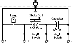
DESCRIPTION: A series RLC circuit, shown in the diagram below, consists of a variable inductor, a fixed capacitor, and a light bulb serving as the resistor. The capacitor and the inductor can be removed from the circuit using parallel switches. When the capacitor is in the circuit, the inductance can be adjusted so that the bulb is brighter, dimmer, or the same intensity as when the capacitor is out of the circuit.
SUGGESTIONS:
REFERENCES: (PIRA unknown.) CENCO Selective Experiments in Physics 71990-682. See Demonstration Reference File for more information.
EQUIPMENT: None.
SETUP TIME:
 |  |  |  | 
|