PURPOSE: To plot a graph of resonance behavior in a very low frequency resonant circuit.
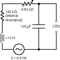
DESCRIPTION: A series RLC circuit, containing a very large inductor, a 0-50 kilohm resistor, and a 100 microfarad capacitor is driven by a sine-wave oscillator as shown in the circuit below. As the frequency of the oscillator is varied between about 0.1 Hz and 0.5 Hz, the resonance in the system is observed to be about 0.3 Hz. The voltage across the capacitor is shown at various frequencies on an oscilloscope. The scope shows both the signal from the oscillator and the signal across the capac itor.

SUGGESTIONS:
REFERENCES: (PIRA unknown.) See Demonstration Reference File for further information.
EQUIPMENT: Large inductor, 0-50 kilohm resistor, and 150 microfarad capacitor oscilloscope. Storage scope available on request.
SETUP TIME: 10 min.
 |  |  |  | 
|