PURPOSE: To demonstrate resonance in an RLC circuit.
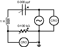
DESCRIPTION: Using the circuit below, the frequency of the oscillator is swept to find the resonance. Both the signal from the oscillator and the signal across the resistor are displayed on the dual trace scope. The capacitor (0-300 picofarads ) and the resistor (0-100 kilohms) in the circuit box are variable. The increase in amplitude of the signal across the resistor and the phase shift at resonance are both easily seen.
SUGGESTIONS:
REFERENCES: (PIRA 5L20.10)
EQUIPMENT: Commercial RLC circuit in box, oscillator, and dual trace scope on scope/TV cart.
SETUP TIME: 5 min.
 |  |  |  | 
|