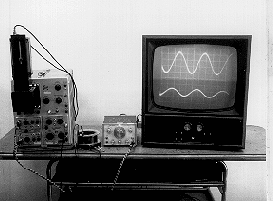

PURPOSE: To demonstrate that the mutual inductance between two coils is independent of which one is the primary.
DESCRIPTION: Two coils with different shape and number of turns are used as the primary and the secondary in a transformer. (Case 1) The oscillator produces an AC current for the primary coil, which is displayed on the upper trace of the oscilloscope. The voltage across the secondary is displayed on the lower trace. (Case 2) The leads are then swapped between the two coils, without changing their positions, and the primary current is adjusted so that it is the same as that for the first case. The secondary voltage will also be the same as the first case.
The voltage of the secondary of a transformer is equal to the current in the primary times the mutual inductance. Because this system is symmetric the mutual inductance going either way must be the same, being only a function of the geometry.
SUGGESTIONS:
REFERENCES: (PIRA unknown.) See Demonstration Reference File for further theory and for circuit details.
EQUIPMENT: Wavetek oscillator, square 250-turn coil and round 1000-turn coil with special wiring harness, dual trace oscilloscope with scope/TV cart.
SETUP TIME: 5 min.
 |  |  |  | 
|