The following experiment is a convincing proof for the transferability
of heat into mechanical energy. For this we have to leave the classroom
and to go to a parking lot. In order to perform the experiment we will
need a car and a bottle filled up with butane gas. Butane gas is
normally used to fill lighters and the refilling container can be used
to fill up a 2 liter plastic bottle.
Commercial plastic bottles are able to sustain a pressure of 800 KPa
but such a pressure will not be necessary. Clean butane condenses at a
temperature of -0.5 °C. If the bottle and the gas has a temperature
of its environment then the pressure within the bottle may exceed that
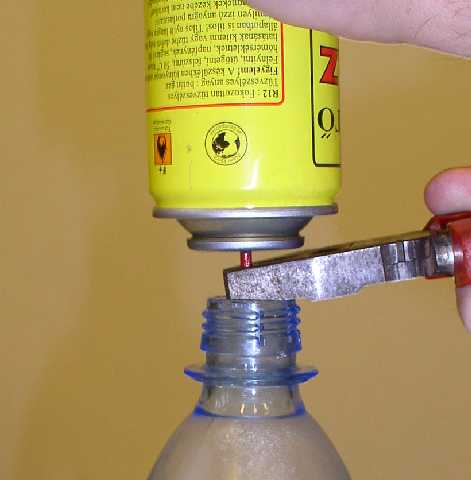
in a tyre of a vehicle. As a first step let us fill the bottle. The
reffiling container should be placed upside down in order to ensure the
flow of the gas to the bottle after having opened it with a clamp. The
butane entering into the bottle will be of mixture of liquid and gas
phase. At the bottom of the bottle there should be liquid butane of 1cm
height. For a short time let the butane to boil in order to extrude all
the air from the bottle. Then the bottle should be closed. On the
bottle we may easily trace the increase of the pressure of butane due
to its boiling process. The steaming up of the outher surface is a
clear evidence that boiling takes heat from the environment. When the
gas attains the temperature of its environment the pressure will be so
large that we may hardly be able to compress the bottle. Afterwards the
bottle and the gas within should be cooled down below the condensation
temperature of the gas. At home we may use the freezer that provides a
temperature of -17°C or we may use dry ice or Nitrogen. The volume
of liquified butane is smaller than that of the gaseous phase therefore
the outer atmospheric pressure squeezes the bottle to a flat shape. Let
us place the bottle to the ground and roll over the vehicle onto the
bottle. Pay attention to place the bottle right below its center,
otherwise side forces would shoot the bottle out of its position. Let
us secure the vehicle with hand brake and chocks. Within a short period
of time the bottle and the gas within acquires the temperature of its
environment and thereupon the pressure increases within the bottle.
When this pressure overcomes the pressure in the tyre the vehicle will
be lifted.
This experiment can be performed using dry-ice. Under this condition
the temperature of the environment can be even below freezing. The
bottle should be placed empty under the tyre of the vehicle with its
opening left accessible. After the securing the car we may put the
dry-ice into the bottle and close it. After heating up the dry-ice
converts into a gas of carbon-dioxide, whose pressure may exceed that
of the previous experiment. Therefore this experiment should be
performed with great care under the supervision of an experienced
person.
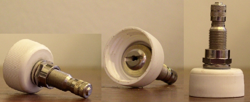
The best is to adapt the bottle cap the following way. A built-in valve
enables to control the pressure of the gas in the bottle. The pressure
increases with increasing temperature - it can be determined according
to the diagram above. As long as the bottle contains all the three
phases - carbon-dioxide is located in its tricritical point - the
pressure is well controled (by the Nature). Do not let the solid phase
to disappear since else the pressure will increase very fast to an
extrame large value. If the solid phase nevertheless disappears you
should run into shelter as fast as possible and do not to spend time on
unscrewing the cap, since the gas will soon undergo an adiabatic
expansion and the pieces of the bottle will fly away in an
unpredictable way.
Experiments with the Dry Ice
Carbon-dioxide is an exciting material. We may demonstrate all the
phases of matter and the phase transitions as well, without the need
for expensive equipment. Carbon dioxide (dry ice) used in the
experiment is an extremely exciting material anyway: all physical
states and state transformations might be demonstrated with it. This is
inspired by the phase diagram of Carbon-dioxide.

Carbon dioxide was first identified in the 1750s by Joseph Black, a
Scottish chemist and physician. Carbon dioxide is a colouriess,
odourless gas. It occurs in the atmospheres of many planets, including
that of the earth. On the earth, all green plants must absorb carbon
dioxide from the atmosphere to live and grow. Dry Ice is frozen carbon
dioxide, a normal part of our earth's atmosphere. It is the gas that we
exhale during breathing and the gas that plants use in photosynthesis.
It is also the same gas commonly added to water to make soda water. Dry
Ice is particularly useful for freezing, and keeping things frozen
because of its very cold temperature: -78.5°C. Dry Ice is
widely used because it is simple to freeze and easy to handle using
insulated gloves. Dry Ice changes directly from a solid to a gas
-sublimation- in normal atmospheric conditions without going through a
wet liquid stage. Therefore it gets the name "dry ice."
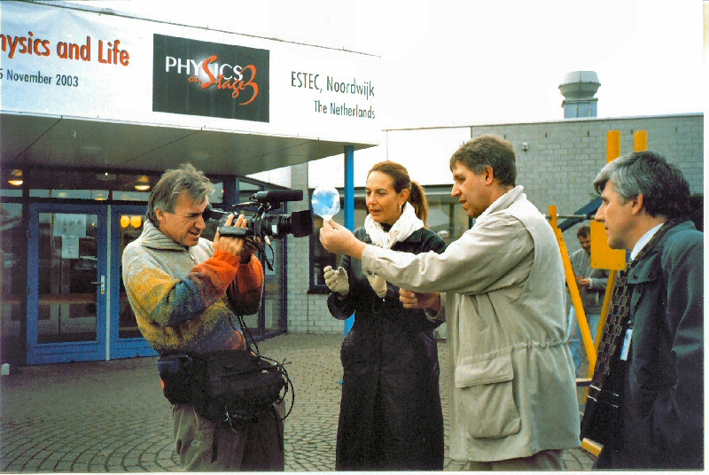
Sublimation of Dry Ice

Opposite to simple expectations this flask contains dry-ice and not
normal ice. Dry-ice is the solid phase of carbon-dioxide. Its
temperature is -78.5 degrees Celsius, and its behavior is different
from what is normally expected since when warming instead of melting
the solid turns slowly to a gas. The resulting gas is colourless and
odourless, human sense-organ have no chance to detect it. The presence
of the gas can be demonstrated by pulling a baloon over the opening of
the flask. Within a short time the balloon will inflate to a sizable
extent. Let us cool down the bottom of the falsk. The refrigerant
should be liquid nitrogen, so the temperature drops far below -78.5
degrees in the flask. The contraction of the balloon shows the
disapearance of the gas. At the bottom of the flask where the
temperature is below the -78.5 degrees solid dry-ice appears, whose
volume is by orders of magnitude smaller than that of the gas. When all
the gas solidifies the flask pulls the balloon in. Let us warm up the
flask. This process will induce the appearance of the gas phase and the
balloon reappears.
Liquefaction of Carbon Dioxide
Dry ice is placed into an PET plastic cylinder. A valve is closed and
pressure in the cylinder increases. When the pressure reaches 511 kPa
it stops increasing and liquid CO2 appears. The liquid
begins to boil and when all solid CO2 is gone, the pressure
increases further. The valve is opened and the pressure drops again,
holding constant for a while at 511 kPa. Eventually solid CO2
reforms, the liquid disappears, and the pressure drops completely.
To melt dry-ice seems to be a process out of question since it
sublimates. Let us warm up dry-ice within a closed, transparent,
pressure resistant vessel. Since the dry-ice is much colder than the
room it takes heat from the environment. As the gas resulting from the
sublimation is not allowed to leave the vessel the pressure increases.
As soon as the pressure reaches the critical value of 511 kPa the wall
of the vessel will be moistened by the dry-ice, a little bit later the
first drop appears which is a clear evidence of the melting process.
The resulting liquid is crystal clear, similar to water. In the course
of time as the liquid accumulates it becomes clear that it is boiling.
All the three phases of the material can be observed in the vessel:
solid, liquid and gaseous together with the process of melting and
boiling. The dry-ice can be found in a curious state: it can be
concidered to be hot and freezing. The valve at the top of the vessel
enables us to let the gas out. Under this condition the liquid starts
to boil intensively, so much that it freezes at the same time. The
frozen dry-ice due to bubbles released during the boiling process
becomes a porosous material. That is called carbonic acid snow that
fills up the complete vessel. Close the valve! Then the pressure may
increase again and we may observe the collapse of the carbonic acid
snow and its melting process.
Critical opalescense of liquified carbon dioxide
Into this glas tube with thick walls carbon dioxide has been closed. At
room temperature two phases may be observed: liquid and gas. This can
be made apparent by moving the tube. Heating it up above 31 degrees
Celsius, carbon dioxide becomes homogeneously gas. Let it cool down. At
a certain moment for a short period all the carbon dioxide becomes
opalescent. The reason for this phenomenon is due to strong density
fluctuations within the gas that leads to a critical phase. At this
point there is no difference between the liquid and the gaseous phase.
There is no meniscus, i.e. surface, no surface tension, the latent heat
of evaporation is zero and the difference between the density in the
liquid and gaseous phase vanishes.
The relationship between magnetism and
electricity
In 1820 a Danish physicist, named
Hans Christian Oersted, noticed that a compass placed near an electric
current in a wire would move, which was caused by the current. He
figured out that electric current was to establish a magnetic field. In
the same year this phenomenon was further explored by Jean Baptiste
Biot and Felix Savart, who then provided its quantitative description.
The effect was poor, many attempted to amplify the effect. First they
made an attempt to increase the electric current later Schweigger had
the following idea: driving the same current by the magnetic pointer
several times will multiply the magnetic effect of the current. He had
an insulated wire coiled around a rectangular wooden frame. This way he
developed a rectangular coil having lots of coils within which the
magnetic fields of each coil got added up. Hence a much lower current
was sufficient to result in moving the compass the same distance. The
magnetic field of this electric frame is in a right angle to the
surface of the frame thus it has the biggest impact on the compass when
its magnetic field is in a right angle to the magnetic field of the
Earth. Upon switching on power the magnetic field within the coil
equals with the vectorial sum of the magnetic field of the Earth and
that of the current. Once power has been switched on the compass will
finally point in the direction of the resulting magnetic field.
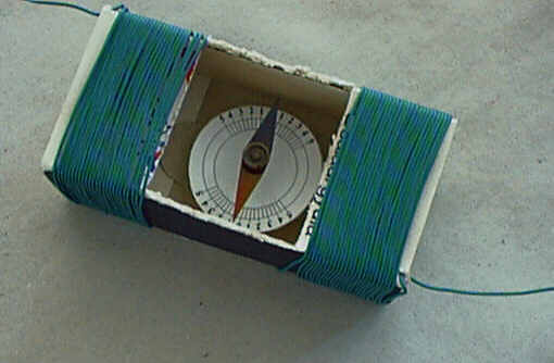
Tangent galvanometer
This is the very source of the
logical idea that the magnetic field of the Earth compared with that of
the current may be used for measuring electric current.
Required materials:
- A large matchbox or- a paper or plastic box,
- A few metres of wires which is- easy to bend, - with lacquer or
plastic insulation,
- A thin sheet of steel in a rhomboid shape - a piece of a
steel measuring tape is also appropriate (easy to magnetise and sheer),
- rubber- or blue-tack,
- pin point needle,
- a round shape piece of paper with a scale,
Process of production:
The central one third in the top of the
matchbox needs to be cut out as shown in the figure. The wire is to be
coiled around the remaining parts.
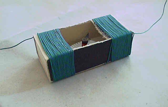
Half of the wires must be coiled around one half of the matchbox,
the other half on the other part. Wires on the right and left must be
coiled in an identical direction (the direction of the magnetic field
of each coil should be the same) and the wire is not to be broken
(uninterrupted coiling). Use rapid glue to tie the wire to the box at
various points. When identifying the number of coils please think of
what is written in the introduction! Increasing the number of coils
will cause the equipment to be more sensitive! I have had 50
coils around the tangent galvanometer shown in the picture and
managed to gain a twist of almost 90 degrees when I measured the
electric current (0,04A) of a torch bulb of 0.2W, 4.5V!
Make the compass using the rubber, the pin point needle, the round
shape of paper (this will serve as a scale) and the rhomboid sheet of
steel. It is easy for us to make the pointer for the compass of a
long-forgotten and therefore unused or broken steel measuring tape.
First cut a bit that can still rotate within the box. Use a thin nail
to make a deepening but be careful not to penetrate through the
material. Then cut it in a rhomboid shape in a mirror image. Place the
sheet on a needle with the deepening pointing upward and the point of
the needle supporting the sheet within the deepening. This way we can
check out whether we have cut out the sheet properly.
The sheet cut out properly will take
a horizontal stand. Only after this should we magnetise the sheet. Take
a magnet and move its north-end from the centre of the sheet to its
edge several times then turn the sheet and the magnet and now move its
south-end from the centre of the sheet to its edge several times. Do
not be surprised! The sheet will move out of the horizontal stand now.
The reason being that the magnetic field of the Earth is not
horizontal. This deviation in angle is called inclination. The magnetic
field of the Earth based upon the calculation of data by Karl Friedrich
Gauss for the first time is as if it had a magnetic rod near its centre
as shown in the figure. In the
figure
HEarth is the magnetic
field force of the Earth H represents the horizontal intensity of the
magnetic field whilst V symbolises the vertical intensity. Having at
look the picture it becomes clear that the magnetic field force of the
Earth depends upon the geographical place, in Budapest its value is H =
0.2 Oersted, the angle of inclination I = 63,3°. Pierce the needle
through the centre of the rubber. Put the scale on. The scale should
carry the tangent values instead of the degrees as we have to calculate
with that anyway.
If possible, we can calibre the scale
with currents already identified.
Now place the rhomboid thin sheet of steel on the head of the needle
(sheet to be magnetised beforehand). So we have got the compass now.
Naturally, should you have a compass at hand you may use that one as
well. Place the compass in the middle of the matchbox (or paper or
plastic box) and you have a tangent galvanometer ready to carry out
measuring.
Usage:
Adjust the matchbox in a way that the
compass (free of current) should be in a right angle to the longer axis
of the matchbox and point at the zero sign on the scale. The two
outgoing parts of the equipment should be connected to the circuit.
After settling we should register the extent the pointer of the compass
turned to.
- We should carry out a test measuring: - the powers of the two
currents are in the same ratio with each other as the tangent of the
angles of the turning they caused.
- We are able to calibre our device based upon an identified
current. Once this has been done we may read specific currents on the
scale.
A few notes and advice to the measuring process:
This device is very sensitive to nearby
objects made of steel and magnet. Therefore, prior to measuring make
sure there is no such object in the vicinity. This becomes even more
important once we have calibrated the device. Another unbeatable
feature of this device is that even high currents are not able to
damage it. We should always read the values when our eyes are in a
right angle to the compass, hence improving our chance to get the exact
number. (parallax error!).