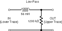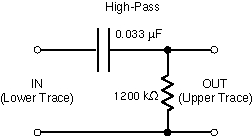

PURPOSE: Demonstrate use of a series RL circuit as a low-pass filter and a series RC circuit as a high-pass filter.
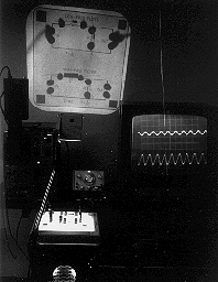
DESCRIPTION: The circuits below have been mounted on a plastic base for use with an overhead projector. Low-pass filter with cutoff frequency f=R/L: The signal is input to the series RL circuit and the output is taken across the resistor. High -pass filter with cutoff frequency f=1/RC: The signal is input into the series RC circuit and the output is taken across the resistor. Values of circuit components are shown on the projectual. In each case the input signal is input into the lower trace of the scope and the filtered signal into the upper trace. Complex waves can also be input to see how removal of some harmonics affects the wave shape.


SUGGESTIONS:
REFERENCES: (PIRA unknown.)
EQUIPMENT: Oscillator, filters on transparent plate, dual trace oscilloscope with scope/TV cart.
SETUP TIME:
 |  |  |  | 
|